
Design for Manufacturing / Welding
Design for Welding: How to Design Fabricated Steel Parts for Weld Quality and Strength
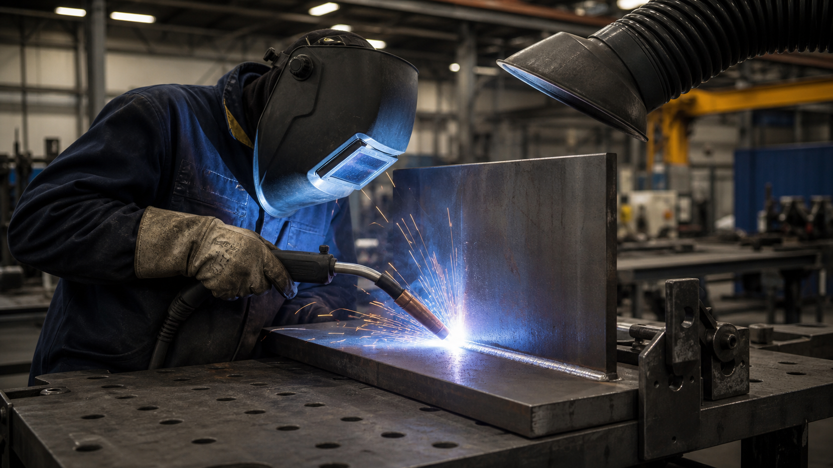
Designing for welding means specifying joint types, clearances, and weld access so the fabricator can achieve strong, consistent welds without rework. The key principles are choosing the right joint for the load direction, allowing physical access for the welding torch and welder’s line of sight, matching material thickness across joints where possible, placing welds symmetrically to control distortion, and defining a weld sequence that builds the assembly in a controlled order. A DFW-ready design reduces weld labor, scrap, and straightening time.
Why Welding Design Matters Before Fabrication
Most weld quality problems originate in the design, not the welding. Joint configurations that don’t allow arc access, wall thickness mismatches that create burn-through risk, and weld placements that fight against distortion are engineering decisions that show up as shop problems. Reviewing a design for weld manufacturability before the first cut saves rework, straightening labor, and schedule time.
Design for manufacturing (DFM) applied to welding is sometimes called DFW, and it’s a discipline separate from weld specification. A drawing can correctly specify weld size, process, and quality level and still be difficult or expensive to weld well because of how components are arranged, what clearance is available, or where welds fall relative to the assembly’s center of gravity.
The consequence of poor weld design isn’t always obvious from looking at a finished part. A weld that was made in a poor access position may be structurally sound but took twice as long to run, which adds labor cost. A weld that generates asymmetric heat may produce a part that meets dimensional callouts after straightening but required two hours of press time to get there. Those costs are real and largely preventable.
Bringing your fabricator into the design review process before drawings are released is the most effective DFW practice available. A shop that has welded thousands of similar assemblies can spot access issues, distortion risks, and joint configuration choices that don’t show up in a stress analysis or FEA review.
Common Weld Joint Types and When to Use Each
The five basic weld joint types are butt, T-joint (tee), corner, lap, and edge. In structural steel fabrication, butt joints and T-joints are the most common. Butt joints join two pieces edge to edge and are used when the joint must develop the full strength of the parent material. T-joints join a plate perpendicular to another and are typically made with fillet welds, which are economical and well suited to structural frames, brackets, and gussets.
Fillet welds are the workhorse of steel fabrication. They’re placed in the corner formed at a T-joint or lap joint and don’t require edge preparation (beveling) on the base material. Fillet weld strength is a function of weld throat size, which is 0.707 times the leg size. A 3/8-inch fillet weld has a throat of about 0.265 inches. For most structural steel fabrication, fillet welds at the correct size for the applied load are the cost-effective choice.
Full-penetration butt welds develop the full strength of the base metal and are used where the joint must carry tension loads across the weld face, or where radiographic or ultrasonic inspection is required. They require edge prep on one or both pieces (typically a bevel or V-groove) and are more time-consuming to make than fillet welds. Specify full penetration only where the load path and design code require it, not as a default.
Plug welds and slot welds are used to join lapped plates where a fillet around the perimeter isn’t practical. A hole is punched or drilled in the top plate, and the weld fills the hole to bond the plate to the piece beneath. These are common in sheet metal and light structural applications where a continuous edge fillet would distort the plate.
Fit-Up Tolerances and Joint Preparation
Weld joint fit-up refers to how closely the mating surfaces of the joint align before welding. Poor fit-up causes voids, incomplete fusion, and burn-through. AWS D1.1 structural welding code specifies maximum root opening and mismatch for different joint types. For fillet welds, a root opening under 1/16 inch is acceptable; over 3/16 inch requires increasing the weld leg size to compensate. Tight fit-up is faster to weld and produces better results.
Fit-up tolerance is controlled by the cut quality and forming accuracy of the mating pieces. Laser-cut edges hold tighter fit-up than plasma-cut edges because the laser kerf is more consistent and the edge is squarer. On assemblies where weld quality and appearance matter, specifying laser-cut components gives the welder a better starting condition than plasma-cut parts with edge dross or kerf angle.
Formed parts (bent on a press brake) have dimensional variation that accumulates across multiple bend operations. A box formed from four bends has small angle errors at each bend that add up to a mismatch at the final seam. Designing formed parts with some weld gap tolerance in the print (rather than requiring a perfect zero-gap butt joint) acknowledges this reality and makes the part easier to produce consistently.
When edge prep is required for groove welds, the bevel angle and root face geometry affect how easily the welder can achieve full penetration. Standard bevel configurations (30 to 37.5 degrees per side on a double-V) are established in AWS D1.1 and give the welder a known starting point. Non-standard joint geometries require welder experience to dial in and usually take longer to weld consistently.
Weld Access and Clearance
A welder needs physical access for the torch (or electrode), line of sight to see the weld pool, and clearance to manipulate the torch angle for proper fusion. Minimum torch clearance for a MIG gun is roughly 3 to 4 inches to the joint, though this varies with torch geometry. Joints inside deep channels, at the bottom of narrow box sections, or behind protruding features may be inaccessible and should be redesigned or addressed with back-weld provisions.
Weld access is easiest to check on a 3D model or a physical mockup, not on a flat drawing. A joint that looks accessible in section view may be blocked by a parallel plate, a gusset, or the workpiece fixture when viewed in three dimensions. If your CAD tool supports it, run a quick interference check on torch envelope clearance around each weld joint before releasing for production.
Interior corners present consistent access challenges. The inside corner of a box weldment is accessible from one end if the box is open, but a closed box has four interior corners and none of them can be reached with a standard torch. Designers who routinely work with weldments learn to specify exterior fillet welds that are equivalent in strength to the inaccessible interior joints, or to leave plug holes in the design that allow access and are subsequently sealed.
Overhead welding is more difficult than flat (downhand) or horizontal welding and produces lower average weld quality from most welders at production speeds. If a joint can be redesigned to eliminate overhead welding positions by changing the assembly sequence or the joint orientation, it’s usually worth the design time. Positioners and turn tables allow a shop to rotate an assembly during welding, converting overhead positions to flat, which is an equipment investment worth discussing with your fabricator for large production programs.
Managing Heat Distortion
Weld heat distorts metal because the weld zone expands when hot and contracts when it cools, pulling the surrounding material toward the weld. The result is angular distortion, bowing, or twist in the finished assembly. Managing distortion starts in the design: symmetrical weld placement, balanced weld volumes on both sides of a neutral axis, and planned weld sequence all reduce distortion before a torch is struck. Distortion that can’t be prevented through design is managed through fixturing and post-weld straightening.
The amount of distortion produced by a weld is related to heat input, which is a function of weld size, travel speed, and current. Smaller weld sizes, faster travel speeds, and lower heat input procedures all reduce distortion. For structural welds that must develop a specific load capacity, there’s a minimum weld size defined by the design, but for any weld that’s been oversized “just to be sure,” reducing the weld size to the design minimum reduces distortion without sacrificing structural performance.
Thick-to-thin transitions are a common distortion source. Welding a 1/4-inch plate to a 1-inch plate requires heat input appropriate for the 1/4-inch side to avoid burn-through, but the 1-inch plate acts as a large heat sink that draws heat away from the joint. The welder compensates by adding heat, which drives distortion in the thin plate. Design alternatives include adding material to the thin side, using a taper transition, or considering mechanical fastening for joints where weld distortion is unacceptable.
Weld Sequence and Symmetry
Weld sequence is the order in which welds are made on an assembly. A good sequence builds welds in a way that keeps the assembly in balance, so that each weld’s distortion is partially offset by subsequent welds on the opposite side. Backstep welding, balanced sequence (alternating sides on a symmetric joint), and skip welding are common techniques for controlling distortion through sequence management.
For symmetric assemblies, the most effective distortion control is welding in balanced pairs: make a weld on one side, then immediately make a corresponding weld on the opposite side before the first weld has fully cooled. This approach uses the thermal gradient of the first weld to pre-load the assembly in the direction opposite to the second weld’s expected pull. The two distortions partially cancel rather than compound.
Weld sequence should be documented on complex assemblies, either on the print or in a separate welding procedure specification. A sequence that works well should be repeatable across operators and production runs. Leaving sequence to welder discretion on a complex assembly produces batch-to-batch variation in final dimensions, particularly on long weldments like frames and beams.
Weld symmetry is a design principle that supports sequence control. If an assembly can be designed so that every weld joint has a mirror-image weld on the opposite side, the assembly is set up to be welded in balanced pairs. Asymmetric assemblies are sometimes unavoidable, but they require more careful sequencing and more post-weld straightening to achieve dimensional conformance.
Sending a DFW-Ready Design to Paragon
A design is ready for fabrication when it includes a fully dimensioned print with weld callouts per AWS A2.4 symbols, material specifications, finish requirements, and any critical dimensions flagged for inspection. For complex weldments, a model file in STEP or IGES format alongside the PDF print allows the shop to review 3D geometry and check weld access before cutting. Including notes on the weld process, inspection requirements, and known distortion-sensitive features helps the shop build it right the first time.
Weld symbols on a drawing are a precise language. AWS A2.4 defines how to call out joint type, weld type, size, length, pitch, and special instructions using a standardized arrow-and-reference-line notation. Prints that use consistent, correct weld symbols avoid ambiguity and allow the welder and quality inspector to verify the same requirements. Prints that describe welds in notes rather than symbols are harder to check and create more opportunity for misinterpretation.
If your design has features that you know are difficult to weld, a DFM conversation with the fabricator before print release is the most efficient path. Most shops are glad to review a model or sketch before formal quoting to flag issues while they’re still inexpensive to address. The conversation typically takes minutes and can save hours of rework. You can reach our welding team through the contact page or by calling 1-800-467-0121.
See our full services overview for the welding processes and structural capabilities available at Paragon, and our welding types page for a breakdown of MIG, TIG, stick, and flux-core welding and when each is used in structural fabrication.
Design Review Before You Quote
Send us your model or print. Our welding team can flag access issues and joint configuration concerns before you cut a single piece, so the production run goes smoothly.
Frequently Asked Questions
What joint type is strongest for steel fabrication?
A full-penetration groove weld in a butt joint develops the full tensile strength of the base metal, making it the strongest weld joint for tension loads across the joint face. For shear loading and most structural connections, a properly sized fillet weld in a T-joint or lap joint is fully adequate and significantly less expensive to produce. The strongest joint is not always the right joint: specify the joint type based on the load direction and the applicable design standard, not by defaulting to full penetration everywhere.
How much clearance does a welder need to access a joint?
A standard MIG welding gun needs roughly 3 to 4 inches of clearance from the nozzle to the joint, plus room to move the gun through the travel angle (typically 5 to 15 degrees from perpendicular). TIG torches require similar clearance. Stick electrodes are more flexible but still need room to maneuver and feed. As a design rule, any joint inside a channel or box section that cannot be reached with a straight 12-inch object from an open end is likely to present weld access problems worth reviewing before fabrication.
Can I specify weld size on my drawing?
Yes, and you should for structural welds. Weld size is specified using the weld symbol leg size (for fillet welds) or weld throat depth (for groove welds) on the drawing per AWS A2.4. The fabricator is responsible for achieving that size and for selecting an appropriate procedure and filler metal. If you have minimum filler metal strength requirements or code compliance requirements (such as AWS D1.1 for structural steel), specify those on the drawing or in the purchase order so the shop can document procedure qualification accordingly.
Does weld placement affect part flatness?
Yes, significantly. Welds placed on only one side of a plate or assembly generate asymmetric heat that pulls the assembly toward the weld side. Longer welds and higher heat input amplify this effect. Designing welds in balanced pairs on opposite sides of the assembly’s neutral axis is the most effective way to minimize distortion-driven flatness loss. When asymmetric welding is unavoidable, plan for post-weld straightening and discuss the required flatness tolerance with your fabricator before the job starts.
or call 1-800-467-0121